The Warhound kit (EG link) is a nice little kit, it goes together great. Unfortunately after creating some wreckage on the bases for the models I realised I needed to adjust the legs to make the Warhounds fit their bases. This post is about how I went about straightening a Warhound Titan’s leg.
I would normally create a base for a model at the same time as I was building the model. This is so that I could make the most of the ability to position the model’s parts with minimal converting needed (a good example of this is the Warlord Titan’s base). Over Christmas I got carried away while building the bases for my pair of Warhounds. As I did not pay much attention to the models themselves. So now I have to make both the Warhounds fit the bases. The first thing I needed to do for the Warhounds was to straighten a leg, effectively making it slightly longer, to allow the titan to be stepping up to a higher height than the legs would normally allow.
Time to break a leg…
Four legs come in the box, and from these there look to be 3 unique leg positions (the first one and the last one in the image below look the same to me).

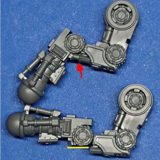
Picking one of the legs to work with, I decided where to place the cuts to allow the leg to be adjusted with the minimum amount of damage caused. For the lower rotating joint I chose to cut between the armour plate and the cylinder forming the joint (hub). I used a jewellery saw* with a small blade width to get as neat a cut as possible. Two cuts were used, the first starting at the red arrow, and the second starting at the yellow arrow (see image below).
I then cut the upper knee joint above the knee hub. I cut as neat as I could around the hub to avoid much clean-up work. Again this was completed in two cuts, the first at the red arrow, the second at the yellow arrow. The jewellery saw allows you to change direction and attempt to cut curves. But this location does have an armour plate to glue in place so maybe some damage might be hidden after completing the build.

I then tidied up the cut surfaces with an emery board, then sculpted detail back on to the hubs to match the detail already there (ie the little ridges). Although, I’m not so hot at sculpting.

While cutting the lower leg I realised the ‘as modelled’ limits to the extension of the titan’s leg. If the hydraulics (assuming that is what they are of course) provide the motive force to actuate the legs then the joint can’t actually straighten that far because of the line of action of the piston would interfere with the joint (in image below, red arrow pointing at the actuator, yellow line of action tangential to hub). So to get as long a leg as possible I’ll have** to adjust the piston attachment to the lower leg.
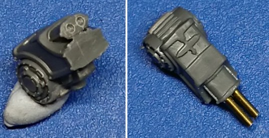
I cleaned up the cut surface and marked two pilot holes into the end of the plastic part where I wanted the piston rods to be. I did two on the lower location because of the width of the part cut off. I opened the holes up with a 1mm drill bit to accept 1mm brass rod and cut it to length.
Then, because of the small contact area of the leg joint, I also pinned the two parts of the leg to add a bit of strength to the joint . I drilled holes in both sides of the joint and used 0.8mm diameter brass rod to pin them together.

The upper leg also had the same issue as the lower leg mentioned above. As the cylinder barrel for the ‘hydraulics’ is wider I decide to use a section of brass rod and brass tube. The position to drill was marked with the point of a knife (red arrow on image below). Then a pilot hole was drilled, and this was then opened up to 1.5mm to match the brass tube’s diameter. The tube was cut to length and glued in place. The tube accepts 1mm diameter brass rod, which was cut to length and glued in place. This gives a nice stepping down effect like a telescopic strut.
I also pinned this joint, again because of the small contact area. Putting a 0.8mm pin through the centre of the joint.

The image below shows the pin being dry fit to check the leg before gluing (top). Once glued in place I then attempted to sculpt some ends on to the brass rods representing the hydraulics (bottom).

Last job was to tidy up the loose ends of the pistons, squaring them off by carving them a little with a knife (again I have no idea if that is what they are, they could be power cables, fibre muscle bundles, something else). I just sculpted some ends on to them, to make them look finished off. I also filled some gaps in the legs where they had been cut. Here is a pic of the two finished straightened Warhound legs.

What’s next?
Well I need to adjust the positioning of the toes on the feet and to increase the bend of leg’s knees. Maybe they’ll be posted up next, if not hopefully the finished Warhounds will be.
*I bought my jewellery saw off eBay years ago with a bunch of spare blades (they do break easily). I can’t find my exact one, but this is very similar looking, if you are not sure what I’m talking about.
**I don’t have to, but I do, if you know what I mean 😉

Pingback: Adeptus Titanicus: Warhound Leg Adjustments Strike Back | Splayed Paint Brush