This article is about how I went about converting my Farrow Roadhog, who I have nicknamed Mad Max. Again it was first published on the web a few years ago but the website it was on has disappeared from the web.

Mad Max the Farrow Roadhog
Parts List :
- 1x Road Hog
- 1x Model engine set Zinge Industires
- Track set components Zinge Industries
- Driller Grappler arm and claw
- Madhammer’s helmet visor
- 2x Karchev skirt frame thingys
- 2x Hammersmith hammer heads
- 2x Thunderhead struts
- Khador Berserker shoulder armour
- Drago shoulder plate & spikes
- Brass rod and tube, I used one size of brass rod which fit snugly inside the first size of brass tube, which in turn fit inside the second larger brass tube.
- Various sundries: Plasticard, and some old electrical wire
To quote a favourite film of mine “that’s a big list!”
I didn’t sit down with the above list and build Mad Max in one go, I assembled the different sections as and when I had worked out how I wanted things to go together and scavenged the parts I thought I needed. With that in mind a step by step tutorial on how I assembled the Road Hog isn’t possible, as it didn’t get built like that. So I have broken the tutorial down into the different modules that make up the completed Road Hog and hence this is not the sequence I actually built or took the pictures in.
Tracks
Make a note that the brass rod fit snugly inside the brass tube.
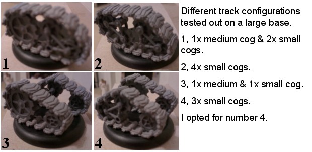
After messing around with the track set available from Zinge Ind. I quickly decided what size wheels I needed. After that I dry assembled a number of different track configurations, I settled on a triangular wheel arrangement. To complete both track assemblies I used 3 boogie sets and one track link set plus some brass rod.
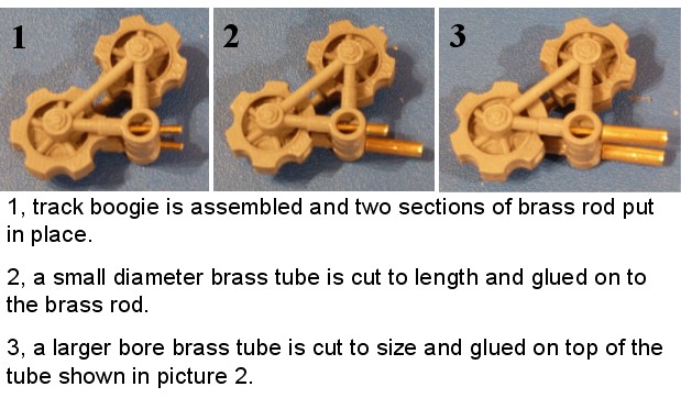
I then cut two short sections of the first size of brass tube to match the length of the previous brass rod pins. I glued these on to the ends of the brass rod, so that the tube was flush with the track hub. Using the second larger diameter brass tube cut two lengths about 10mm long and glue these onto your previous work, again keeping them flush with the hub. Now dry fit the tracks and the wheel assembly so you can judge how far back the rear wheel needs to be. Also take note of the rear wheels orientation.
Cut the wheel hubs off the 2nd boogie components. Remove the struts so you just have the wheel hubs. Now drill into the wheel hub and glue in a section of brass rod. The using the smaller diameter brass rod cut a section about 12-14mm long (too long is better than too short at the moment) and glue onto the brass rod so that the ends are flush with the wheel hub. Keep in mind the orientation of the wheel you noted before (mine where placed so that there was a cog tooth a the top and bottom) glue the wheel to the hubs so that the brass tubing will connect to the other half of the wheel assembly. Dry fit the whole assembly again, if the two sections are too long then cut them down to fit. Once you are happy with the fit glue the brass rods into the brass tubes.
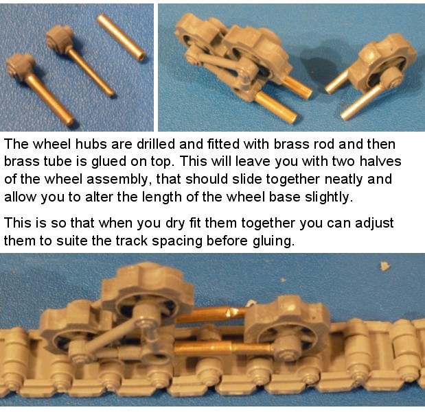
The last thing needed to complete the wheel assembly is to cut two sections of brass tube to fit snugly between the rear wheel hub and the upper wheel hub. In one end of the tube i glued a short section of brass rod, it only extended from teh tube by about 1mm. I drilled two shallow holes at the place where the brass rod would touch the rear hub (one on each side of rear hub). Glue the strut in place between the upper and rear hubs. Finally wrap the track around the wheel assembly and glue into place.

Chassis & Engine
So I had two assembled track units and needed a way to hold them together and attach the engine and Road Hog torso. I puzzled about this for a while, rummaged around in my bits box and played with a number of various bits until I came up with an idea I was happy with.
I glued two Hammersmith hammer heads together with the attachment point for the shafts pointing down. I cut a section of plastic bar to be slightly longer than the width of the hammerheads and glued it to the bottom of the hammer heads beside the shaft attachment points. At each end of the plastic bar I placed a pin to connect the tracks at the centre of the upper most track wheel hub. A section of plastic rod was cut to the same length as the plastic bar to form the rear axle between the rear track wheel hubs. The hydraulic struts from the Thunderhead just happened to be the perfect length to go from the lower central track hub to the hammer head attachment point. Glue all the joints to attach the track assemblies to the chassis.

The engine was dead easy to put together, the only difference I made in assembling it was to reverse the exhausts and the air intake. The reason for doing that was because the belt and tensioner part looks great but didn’t look like it would fit on the final model. So I ended up mounting the engine the other way round. The engine itself is just sat on the rear axle and the back of the hammerheads. Before gluing it in place I made sure that the angle of the engine matched that of the tracks, and some plastic bar was glued to the bottom of the engine to lift it up high enough so the exhausts didn’t touch the tracks.

Cradle
To blend the organic piggy torso into the mechanical chassis I decided to build a cradle for the body to sit on. I messed about with this a lot before I got something I was happy with. I used 2 of the Karchev support frames to form the sides of the cradle. I bent the end sections of each frame in a bit to match the size of the torso better. I then glued these to a square of plastic card, this formed the basic shape of the saddle. I then added some sections of plasticard to make the frame look more substantial and add detail, such as hoisting rings on either side, and more armour plates under the front of the saddle.
Finally a blob of putty was stuck in the middle of the saddle and the torso pushed down onto this whilst still soft into the position it will finally be glued in. Once hardened the putty forms a good seat to glue the torso onto which will be in exactly the right position that you want it to be.

Head & Torso
As I was turning the Road Hog into an engine on tracks I figured the boiler on his back was a bit redundant, so I filled the gap on his back with putty and sculpted a spine (as I hadn’t decided at that point what was going to replace the original boiler).
While that was curing I fitted the visor to the head, all that was required was a bit of hand pressure to ‘flatten’ the visor slightly. This enabled it to sit snugly on the Road Hog’s leather goggles with no other modifications needed. However with the visor in place I found I needed to remove some of the Road Hog’s Mohican. I gave him just enough of a haircut to allow the head to fit in place. The head was then pinned on, and the gaps around the back of the head and around the helmet filled with putty. Finally I sculpted some hair to disguise where I had cut some away above his helmet. I also extended his hair down his spine a little way too.

The torso was glued to the cradle, as mention above, via the hardened putty. Any gaps surrounding the joint were then filled with putty and sculpted to look like folds of fat (the pig has no legs so its not like he’s going jogging to loose weight). I also added some wire going into his belly to look like tubing at this point too. Maybe that big V8 runs on piggy methane.

Tanks
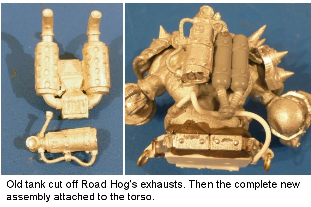
The tank below the exhaust of the original model’s boiler was removed with a saw. This tank was then glued to an old pair of WH40k plastic Leman Russ flamer tanks. This assembly was glued to the back of the torso and connected with short sections of wire (and a little more putty work) to representing hoses connecting up with the body.
Arms & Shoulders
The left arm is the stock flamer and shoulder armour. The right arm’s claw has been replaced with a Grappler from a Gordson Driller. The right arm’s ball socket joint was cut off just below where the organic arm becomes bionic. After cutting the upper arm section off the grappler, the two fit together perfectly. I did this joint as the contact point is pretty small for a large fist to hang off.The upper shoulder armour plate is one of Drago’s armour plates. The lower one is from a standard Berserker warjack. A small blob of putty and some glue was used to place the armour plates in the required place on the shoulder.

Finally
The torso being all metal and the chassis mostly being resin/plastic makes the model very top heavy. With this in mind I tried to make the base, and the positioning of the tracks on the base, help to minimise the risk of the model toppling forwards. I did this by placing the tracks on the base as far back as possible so that most of the weight is over the middle of the base. I also made the base so that model is tilted slightly backwards further moving the weight back over the base.
The upper half of the model is connected to the lower half with two pins. One in the middle of each hammer head of the chassis. These pins help anchor the cradle in place on the chassis.
I painted this model in two parts, the upper and lower half separately.
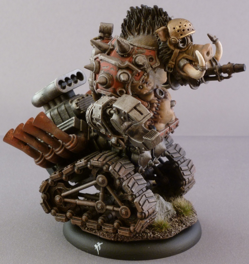
Mad Max the Farrow Roadhog
